How to Test for Continuity with a Digital Multimeter – 2026
TL;DR
Continuity means a complete electrical path exists between two points. To test for continuity with a digital multimeter, de-energize the circuit, set the meter to continuity mode (the symbol looks like a sound wave), and touch the probes to both ends of the component. A beep with near-zero resistance means the path is good. No beep and an “OL” reading means the circuit is broken.
What Is Continuity?
Continuity is the presence of a complete path for electrical current to flow. That’s it. When you test for continuity with a digital multimeter, you’re asking one simple question: are these two points electrically connected?
Think of it like checking whether a garden hose has a kink. Water (current) can only flow if the path is clear from end to end. If a wire is broken inside its insulation, if a fuse has blown, or if a switch has failed, the path is broken and current cannot flow.
Two distinctions worth knowing early:
Continuity is not the same as conductivity. Continuity is binary: a path either exists or it doesn’t. Conductivity is a material property that describes how well a material carries current once a path is present. Copper has high conductivity. Rubber has essentially none.
Voltage can exist without continuity. A wire might have 120 volts on one side, but without a return path, no current flows. This is why continuity testing matters. It confirms the circuit is actually complete.
For aspiring technicians, this is one of the first diagnostic skills you’ll use on the job. Whether you’re troubleshooting a dryer that won’t heat or tracing a fault in HVAC wiring, testing for continuity is foundational to every trade program.
What You Need
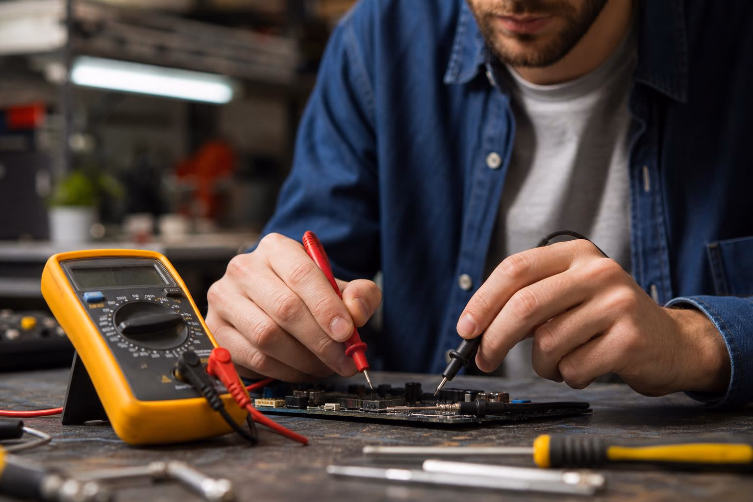
- A digital multimeter (DMM) with continuity mode. Most modern meters have this. Look for the symbol on the dial that resembles a diode with propagation waves around it, like sound coming from a speaker.
- Test leads in good condition. Dirty or frayed probe tips cause intermittent and unreliable readings. Inspect them before every use.
- Safety gear. Insulated gloves and eye protection, especially when working near circuits that were recently energized.
If your multimeter doesn’t have a dedicated continuity symbol, don’t worry. You can use resistance mode instead (more on that below).
Step-by-Step: How to Test for Continuity with a Digital Multimeter
Follow these six steps every time. The order matters.
Step 1: De-Energize the Circuit
This is not optional. Testing for continuity on a live circuit is the single most dangerous mistake you can make. It can damage your meter, blow a fuse inside it, or create a serious safety hazard. Disconnect power at the breaker or unplug the appliance. If the circuit contains capacitors, make sure they are safely discharged before touching anything.
Step 2: Connect the Test Leads
Insert the black test lead into the COM (common) jack. Insert the red test lead into the jack labeled VΩ (sometimes labeled VΩmA). This is standard across virtually all digital multimeters.
Step 3: Select Continuity Mode
Turn the dial to the continuity test position. On most meters, this mode shares a spot with the resistance (Ω) function. You’ll see the sound-wave symbol near the ohm symbol.
Step 4: Verify the Meter Is Working
Touch the metal tips of your red and black probes together. You should hear an immediate, steady beep and see a resistance reading near zero (usually less than 1 Ω). If you get nothing, check that your leads are in the correct ports. A weak battery can also cause problems.
This verification step takes two seconds and saves you from chasing phantom problems with a malfunctioning meter.
Step 5: Test the Component
With the circuit de-energized, place one probe on each end of the component you’re testing. The position of the leads doesn’t matter for continuity, but the component must be isolated from the rest of the circuit. If it’s still wired in, parallel paths through other components can give you false readings.
The meter will beep if it detects a complete path. It will display “OL” (open loop) or “1” if no path exists.
Students in technical training programs can practice these procedures in virtual lab simulations before working on real equipment, which builds confidence without risk.
Step 6: Turn Off the Meter
When finished, turn the multimeter off to conserve battery life. Leaving it in continuity mode drains the battery faster than you’d expect.
How to Read the Results
This is where many beginners stop too soon. The beep is useful, but the number on the screen tells the real story.
| Reading | What It Means |
|---|---|
| Beep + 0 Ω (or near zero) | Good continuity. Complete path exists. |
| OL / 1 / Open | No continuity. The circuit is broken. |
| Beep + 15–50 Ω | High-resistance continuity. Path exists but is degraded. |
The “Beep But Bad” Scenario
A beep with a resistance reading of 0.5 ohms is very different from a beep with 45 ohms. Most multimeters will beep for any reading between 0 and 50 ohms, though the exact threshold varies by model. On a Fluke 87, for example, the beep triggers at 40 Ω or less on the 400 Ω range setting.
High-resistance continuity is a major red flag. Practitioners on forums describe this as “a connection on the verge of failure.” The cause is usually invisible: corrosion inside a connector pin, a poorly crimped terminal that’s overheating, or a frayed wire where only a few strands of copper remain. The circuit technically works, but it’s unreliable and potentially dangerous.
Bottom line: Always look at the resistance value. Don’t rely on the beep alone.
Continuity Mode vs. Resistance Mode
This trips up a lot of beginners. Both modes measure resistance, but they serve different purposes.
| Feature | Continuity Mode | Resistance Mode |
|---|---|---|
| Purpose | Quick pass/fail check | Precise resistance measurement |
| Output | Audible beep + resistance value | Resistance value only |
| Speed | Instant feedback | Requires reading the display |
| Best for | Checking connections, fuses, switches | Measuring specific component values |
If your multimeter lacks a dedicated continuity mode, you can still test for continuity. Turn the dial to resistance (Ω), set it to the lowest range if your meter has manual ranging, and touch the probes to the component. A reading near zero means continuity. “OL” means no path.
One important caution from practitioners on the All About Circuits forum: continuity mode injects a small voltage to test the path. On most meters this is harmless, but if you’re testing sensitive PCB components rated for low voltages (1.6V, 3.3V), a meter injecting 9V could cause damage. For delicate electronics, check your meter’s specifications first.
Common Mistakes to Avoid
Testing a Live Circuit
Worth repeating because it’s the most common and most dangerous error. When testing for continuity, never connect the meter to a circuit that has power connected. You’ll get incorrect measurements at best and damage yourself or your equipment at worst.
Not Isolating the Component (Ghost Readings)
This is the mistake that frustrates experienced technicians, not just beginners. If the component you’re testing is still connected to the rest of the circuit, your meter’s test current can find an alternative “sneak path” through other components wired in parallel.
Here’s a real-world example that practitioners describe: you test a switch you suspect is bad, but the meter beeps anyway. The current is bypassing the switch through a nearby relay coil or indicator light wired in parallel. Your meter sees a complete circuit and gives a false positive. The only way to get a trustworthy reading is to disconnect or isolate the component.
Ignoring the Resistance Number
Some technicians rely entirely on the beep. A beep is a beep, right? Wrong. A beep at 0.3 Ω is a healthy connection. A beep at 40 Ω might indicate a wire that’s about to fail. Train yourself to read the display every time.
Dirty or Damaged Probes
Poor contact between test leads and the conductor causes intermittent or false open readings. Clean your probe tips regularly and replace leads when the tips show visible wear.
False Beeps from Capacitors
Capacitors in a circuit can produce a brief beep followed by silence. The capacitor acts like a short for a split second as it charges, then behaves like an open circuit once full. This confuses beginners regularly. If you hear a quick beep that immediately stops, you’re likely hearing a capacitor charge, not a true continuity reading.
Real-World Applications in the Trades
Appliance Repair
Continuity testing is the most common multimeter task in appliance diagnostics. Fuses, thermostats, switches, heating elements, sensors, and solenoid coils are all tested this way.
When testing a two-terminal switch, remember that switches are either normally open (continuity only after activation) or normally closed (continuity before activation). If you don’t know which type you’re testing, you’ll misinterpret the result.
Some components have variable resistance depending on temperature. A refrigerator bimetal thermostat or a dryer ignitor, for example, will read differently at room temperature than at operating temperature.
If appliance repair interests you, read the full appliance repair technician career guide for a deeper look at what the work involves day to day.
HVAC/R
Continuity testing is essential for checking compressor windings. A low resistance between the appropriate terminals confirms intact windings. An infinite reading (OL) between terminals means the winding is broken. A low resistance reading between any winding terminal and ground indicates a short to ground, which is hazardous and requires immediate attention.
Technicians also use continuity to test contactors, relay coils, and safety switches throughout HVAC systems. For more on this career path, see the HVAC/R technician career guide.
General Electrical Work
Extension cords, household wiring, circuit breakers, and automotive wiring harnesses are all commonly tested for continuity. It’s also the fastest way to check whether a fuse has blown: touch one probe to each end of the fuse. A beep means good. Silence means replace it.
Pro Tips for Better Diagnostics
The Wiggle Test for Intermittent Faults
The most frustrating problem any technician faces is the intermittent fault, a connection that tests fine one moment and fails the next. This usually happens when a wire is broken internally but the copper strands are still touching just enough to register continuity. When the machine vibrates or a cable shifts, the connection breaks.
The fix: perform your continuity test while gently manipulating the wire or connector. Bend it, wiggle it, apply light pressure at stress points. If the beep cuts in and out, you’ve found your intermittent fault. This technique is rarely mentioned in basic guides, but it’s something experienced technicians use constantly.
The Split-Half Method
When troubleshooting a long circuit or wiring run, testing every single connection point is slow. The split-half method is faster. Test continuity at the midpoint of the circuit. If you have continuity to the midpoint, the fault is in the second half. If you don’t, it’s in the first half. Keep splitting the faulty section in half until you isolate the problem. This approach dramatically cuts troubleshooting time on complex systems.
Check Your Probes First, Every Time
Make it a habit to touch your probes together before every testing session. It takes two seconds and confirms your meter and leads are working properly. Professionals do this reflexively.
Building these habits early makes a real difference. Programs that include virtual reality lab practice let students develop proper testing technique in a safe environment before working on live equipment.
FAQ
Can you test continuity on a live circuit?
No. Never test for continuity on a live (energized) circuit. It can damage your multimeter, produce incorrect readings, and create a serious safety hazard. Always disconnect power and discharge any capacitors before testing.
What does OL mean on a multimeter?
OL stands for “open loop” or “overload.” In continuity mode, it means there is no complete path between your two probe points. The circuit is broken.
Is continuity the same as zero resistance?
Not exactly. Continuity means a path exists, and it will typically show very low resistance (under 1 Ω for a good connection). But a meter will beep for readings up to 40 or 50 ohms depending on the model. Zero resistance is the ideal, but any very low reading indicates a healthy connection.
What if my multimeter doesn’t have a continuity mode?
Use resistance mode instead. Set the dial to Ω and choose the lowest range available. Touch the probes to the component. A reading near zero means continuity exists. “OL” or a very high reading means no continuity. You won’t get an audible beep, but the numbers tell you everything you need.
What is a good continuity reading?
For a wire or direct connection, anything below 1 Ω is excellent. Specific components like heating elements or motor windings will have higher normal resistance values. The key is knowing what the component should read when it’s working properly.
Why does my multimeter beep briefly and then stop?
You’re likely encountering a capacitor in the circuit. Capacitors momentarily appear as a short circuit to the meter’s test current, producing a quick beep. Once the capacitor charges, current stops flowing and the beep disappears. This is normal and does not indicate continuity.
How do I avoid ghost readings from parallel paths?
Always isolate the component you’re testing by disconnecting it from the rest of the circuit. If the component stays wired in, current from your meter can flow through alternative paths, giving you a false positive.
Learning to test for continuity with a digital multimeter is a foundational skill for any trade career in appliance repair, HVAC/R, or electrical work. If you’re ready to build hands-on diagnostic skills through structured training with virtual labs and instructor support, explore the Appliance Repair Technician program or the HVAC/R Technician program at Stoneforge Academy. You can also schedule a call with the admissions team to find the right fit for your goals.
